


Fluke MultiMeter
Fluke Type 73 Digital MultiMeter
Introduction
A multi meter is small portable device that can be used to measure voltage, current resistance, or to test diodes. The Engineering department at Humboldt has a set of Type 73 -III Series III hand held digital multi meter manufactured by Fluke. These meters are over voltage protected against transient voltage spikes and
conform to International Electrotechnical Commission's safety standard IEC 61010. The meters feature an automatic hold to store a reading, and an audible continuity beeper, and can test diodes. A portable hand held multi meter can be used anywhere that quick accurate readings of voltage, current, or resistance are required. The specific applications of this device are numerous.

Figure 1: The Fluke Type 73 MultiMeter
The meter could be used for all of the following, and much more.
- Checking the output of a solar cell
- Measuring the current draw of small AC or DC equipment
- Verifying power supply to a piece of equipment which is not functioning
- Testing an incandescent light bulb
- Reading the voltage signal from pyranometer
- Diagnosing the ignition system on your car when it does not start after you have spent the day in the field in a remote location.
When using a multi meter and interpreting the results gained it is often useful to have a working understanding of Ohm's law.
Operation
The functions on the fuse protected Fluke 73 multi meter are DC voltage, AC voltage, AC or DC current, resistance, audible continuity test and diode test. The multi meter has a multi position selector to select the desired function (See Figure 2). The Fluke meter automatically ranges. On many multi meters each function also has multiple ranges for taking measurements of varying magnitudes. On the Fluke meter the correct range is automatically selected for most measurements. This means that the approximate magnitude of the signal does not have to be known or determined to take an accurate reading. To take a reading the leads must be moved to the appropriate port for the desired measurement. The meter is fuse protected to prevent damage to the device if the incorrect function is selected or if the leads are placed in the incorrect port for the measurement being taken.
The literature for the multi meter lists the accuracy of the meter for the functions of the meter. These values are presented in maximum percent error possible for certain temperature ranges. For the readings to be meaningful the accuracy of the meter must be kept in mind.
Using the Meter
The black (common) lead is always placed in the port labeled COM (see Figure 1). The red lead is placed in one of the other three ports depending on which function of the meter is being used. The units for a measurement are always given in the upper right hand corner of the display screen (see Figure 1).
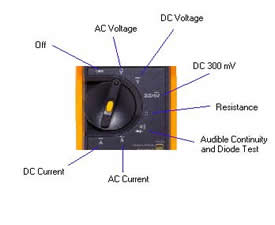
Figure 2: Function Selection on the Fluke MultiMeter.
Measuring Voltage
For all voltage measurements the red lead must be placed in the voltage port which is red on the meter (See Figure 1). The voltage of either alternating current or direct current can be measured. The units for voltage are volts (V), or milivolts (mV). AC voltage and DC voltage are separate functions on the meter each with its own setting on the selection dial as shown on Figure 2. Measuring a voltage which is known to be less than 300 mV the meter should be set on the 300 mV setting (see Figure 2). The AC voltage function reads the RMS (root mean square) voltage of an AC circuit. The polarity of DC voltage can also be determined. If the red lead is on the positive side of the voltage source the meter will read positive voltage. If however the red lead is on the negative side of the source a negative sign will appear on the display indicating that the polarity of the voltage is opposite from the way the leads are connected.
Measuring Current
The Fluke meter can read either AC or DC current up to 10 amps. To read either AC or DC current the correct function must be selected on the function selection dial (See Figure 2). The units for current are amps (A) or milliamps (mA). To read current the red lead must be moved to one of the two ports for current. To take a reading that is know to be less than 300 mA place the red lead in the port labeled 300 mA (see Figure 1). To read currents greater than 300 mA, or if the current is not know place the red lead in the port labeled 10A (see Figure 1). For DC current readings as with the DC voltage reading a negative sign will appear if the current is negative. A positive current indicates that current is flowing into the red lead and out of the black lead of the meter, or that electrons are flowing into the black lead and out of the red lead as illustrated in Figure 3.
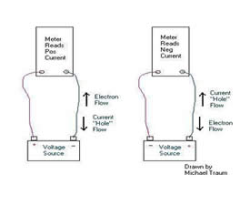
Figure 3: Current Flow Diagrams
The meter is actually measuring electron flow when current is measured. However the convention is to talk about current flowing as positively charged particles, which do not actually exist.
This convention can be traced back to the time of Thomas Edison, who arbitrarily selected a positive current as being the flow of positively charged particles, before the electron had been discovered. It is now understood that electrons flow carrying current, Edison's convention however has stuck. We will probably be taking about the flow of "electron holes" for many years to come.
Measuring Resistance
The resistance of any circuit can be measured in the units of ohms (W), miliohms (mW), or megaohms (MW). Ohm ranging on the Fluke multi meter is fully automatic. The red lead must be placed in the same port as for reading voltage, that is the red port labeled for ohms (W) (see Figure 1). The function selector must be set for resistance (See Figure 2).
Diode Test and Audible Continuity Test
Testing the condition or polarity of a diode, and the audible continuity test are the same function on the selector (See Figure 2). The meter signals audibly whenever the test leads are connected to a circuit with less than a minimum resistance. This audible signal indicates that the circuit is closed. When a diode is tested the meter is connected first one way, and then the other way. If the diode is good the audible signal will be heard with the diode connected one way, but not with it connected the other way.
Maintenance & Storage
When the unit is not in use the selector switch should be turned to the off position to conserve battery life. If the unit should require a new battery a standard size 9V battery should be used which can be of the alkaline, NiCad, or NiMhd type. If the unit is going to be exposed to rough conditions during transport the leads should be removed from the ports, to avoid breading them off, and coiled to keep them from tangling.
References
How to Apply
So environmental resources engineering sounds interesting, but you are still not sure if Humboldt is right for you? Explore what Humboldt has to offer to both freshman and transfer students.
Paperwork
For paperwork and forms such as major and minor contracts, course planning guides, semester schedules, course rotations, office hours and more, visit our forms page!